

Every FTC team eventually meets the gremlin. The Control Hub reboots, a motor freezes, or the Driver Hub loses the robot. The team swaps parts in a panic, and the problem disappears as mysteriously as it came.
These failures are almost never truly random. They come from three sources: static discharge, electrical noise, and connectors that work loose. This lesson shows where each one comes from and how to get rid of it for good.
One battery, two very different jobs
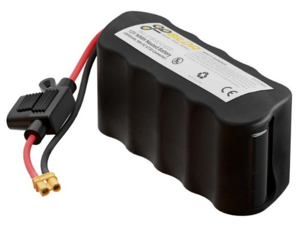
The same 12 V battery feeds the drive motors and the hub's computer. A motor that stalls or reverses can pull 10 A or more in a split second. That spike makes the voltage dip and sends electrical noise along every wire it touches, and your Control Hub and sensors are connected to those same wires.
That's the root tension in FTC wiring: big, noisy motor power and tiny, sensitive digital signals share one small robot, one battery, one metal frame, and often the same wire bundles.
ESD: the invisible zap
Electrostatic discharge (ESD) is the spark you get after shuffling across a carpet in socks and touching a doorknob. Robots do the same thing, at thousands of volts.
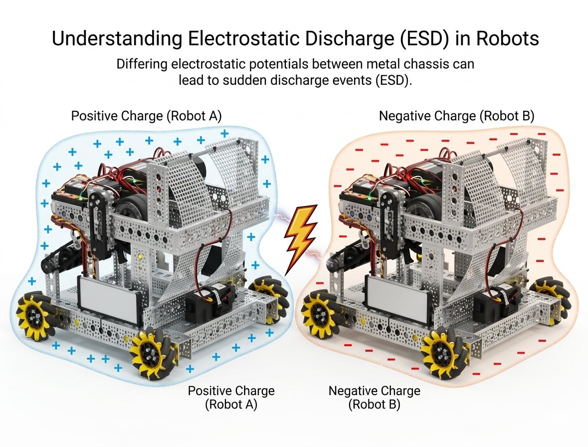
- Charging. Wheels rubbing on the foam tiles move charge onto the robot. This is the triboelectric effect. Wheels that slide build charge faster than wheels that roll cleanly, and mecanum rollers slide a lot.
- Storing. The metal frame holds that charge like a capacitor.
- Discharging. The robot touches another robot, the field wall or a game element, or just gets close to one. A spark can jump a gap of about 10 mm (3/8").
- Damage. If the path for that spark runs through your electronics, the processor crashes and the hub reboots. Sometimes an I2C port is damaged for good.
ESD depends on humidity, the tiles, your wheels, how you drive and who you hit. One match is fine, and the next has three reboots in 30 seconds. Teams blame the code, the battery and the USB cable before they find the real cause.
Four defenses against ESD
FIRST's own guidance stacks several defenses together. No single one is enough.
1. Isolate the electronics from the frame
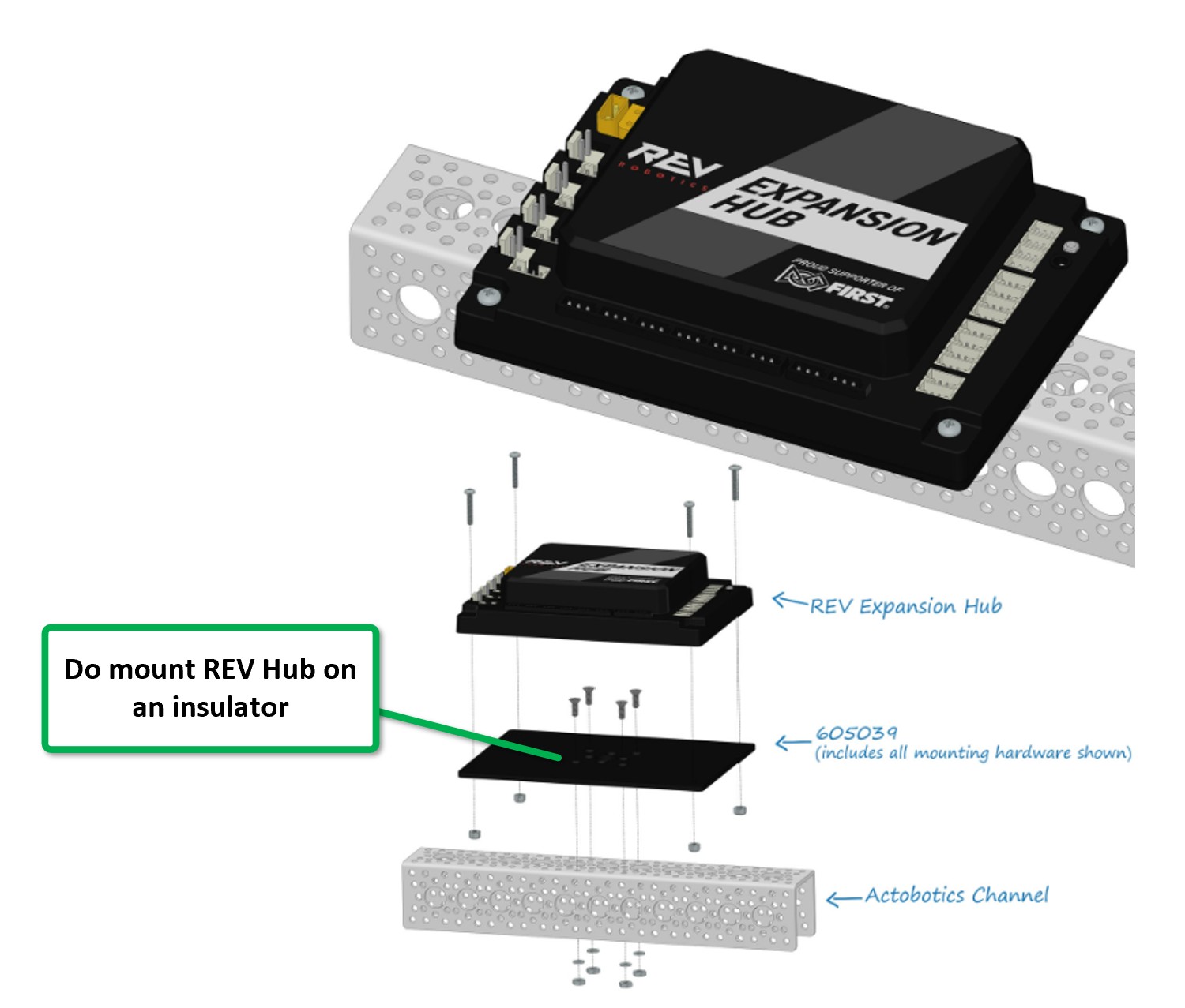
Mount the hubs on something non-conductive, such as thin plywood, PVC, polycarbonate or HDPE, instead of bolting them straight to aluminum. Then look for exposed metal on the electronics: the backs of sensors, the plastic 4-pin sensor connectors, and servo extension joints. Keep those at least 10 mm away from the frame, or wrap them in electrical tape.
2. Ground the electronics to the frame with an approved strap
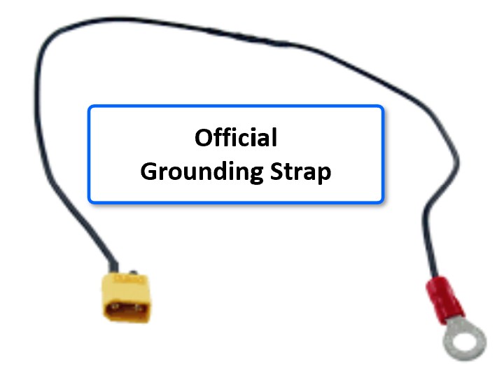
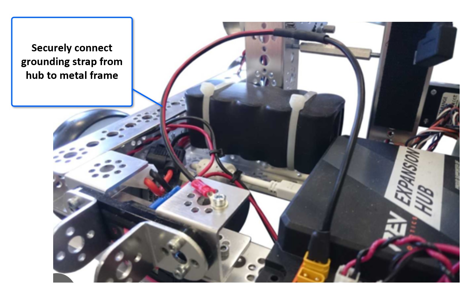
This seems to contradict defense 1, but the two work together. The resistive grounding strap connects the electronics' ground to the frame through a 470 Ω resistor. The frame and the electronics then stay at the same voltage, so charge leaks away slowly instead of building up and jumping across as a spark.
- Plug the strap's XT30 end into a spare XT30 port on a hub.
- Bolt the ring terminal to the frame with a metal bolt. Scrape off any paint or anodizing so it touches bare metal.
- Tug-test it. It must not loosen during a match.
Never make your own. The built-in resistor stops a shorted 12 V wire from dumping current into the frame, and the keyed connector stops anyone plugging 12 V straight into the chassis. The game manual lists which cables are legal.
3. Add ferrite chokes to signal cables
A ferrite choke is a snap-on ring that blocks sudden current spikes. Put one on each sensor, encoder and servo cable, and use USB cables that already have chokes. They're cheap and we keep a bag of them in the pit.
4. Insulate the outside of the robot
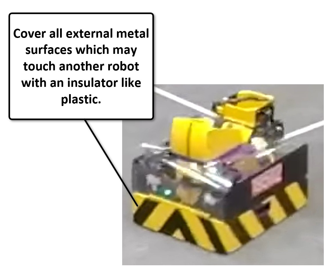
Discharges happen at points of contact. Cover any metal that could touch another robot, the wall or a game element. Polycarbonate panels, wooden or rubber bumpers, and electrical tape on claw tips and channel ends all work. If there's no metal-to-metal contact, there's no path for the spark.
Isolate the hubs and keep exposed connectors away from metal. Ground the electronics to the frame with an approved resistive strap. Choke the signal cables. Insulate the robot's outside. Use all four.
Noise: the sneaky gremlin
ESD hits all at once and crashes things. Noise is quieter. It doesn't reboot the hub. It corrupts sensor readings, makes the IMU drift, or adds random jumps to your odometry.
Motors are noisy. The motor controller switches current on and off thousands of times a second (PWM), so the motor wires broadcast electromagnetic energy like a small radio transmitter. Any wire running alongside them acts as a receiving antenna. The closer the wires and the longer they run together, the worse the crosstalk.
Never coil extra wire
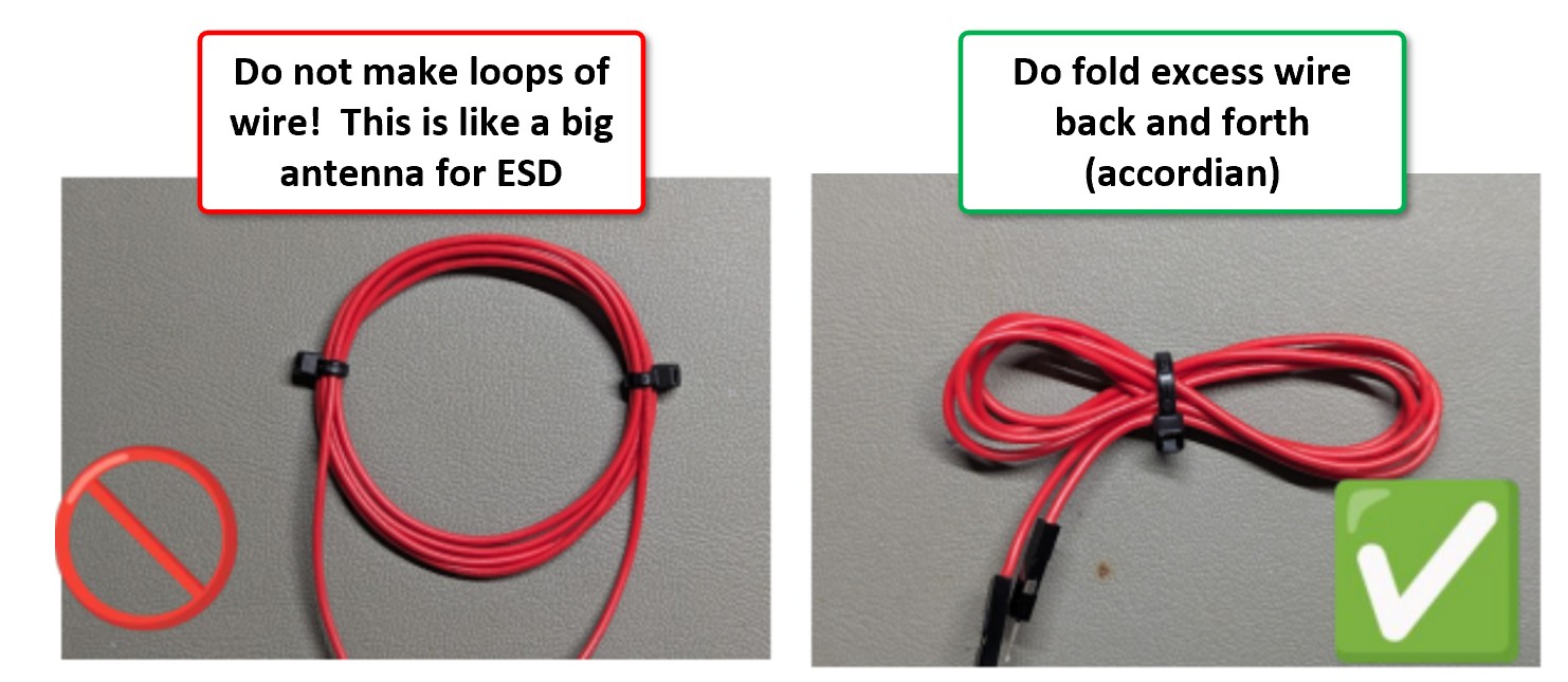
Your instinct with extra wire is to wind it into a neat loop and zip-tie it. Don't. A coil works like an antenna: it collects every changing magnetic field nearby and turns it into voltage on the wire, and a bigger loop collects more. Fold extra length back and forth instead. The noise picked up by neighboring folds mostly cancels out.
Keep power and signal wires apart
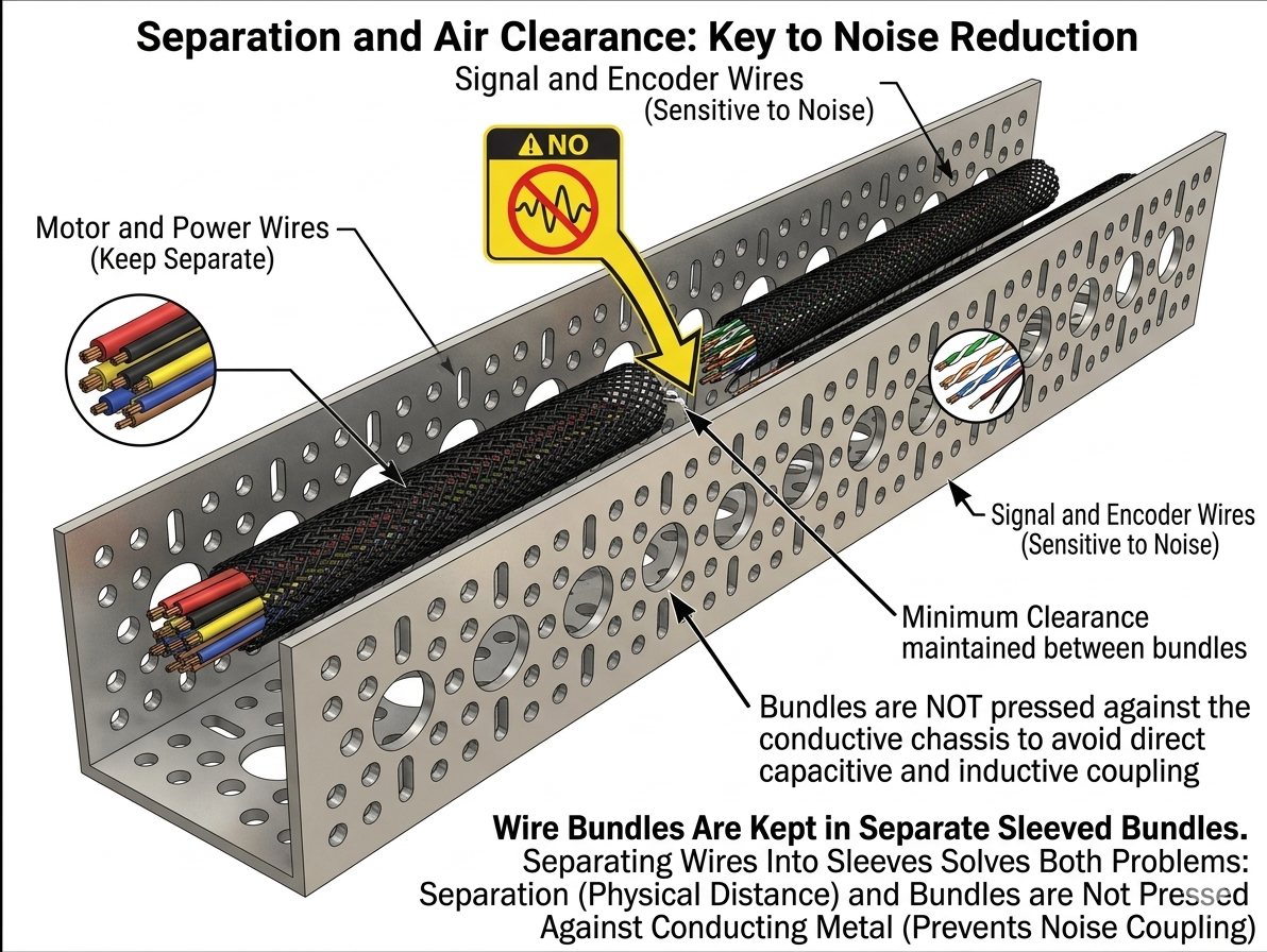
Run motor power wires along one side of the robot and signal wires (encoder, I2C, digital, analog) along the other. Where they have to cross, cross them at 90° to keep the overlap short. Separate braided sleeves help keep the groups organized and apart. Keep motor wires away from USB camera cables too.
Port gotchas
Leave I2C bus 0 for the IMU
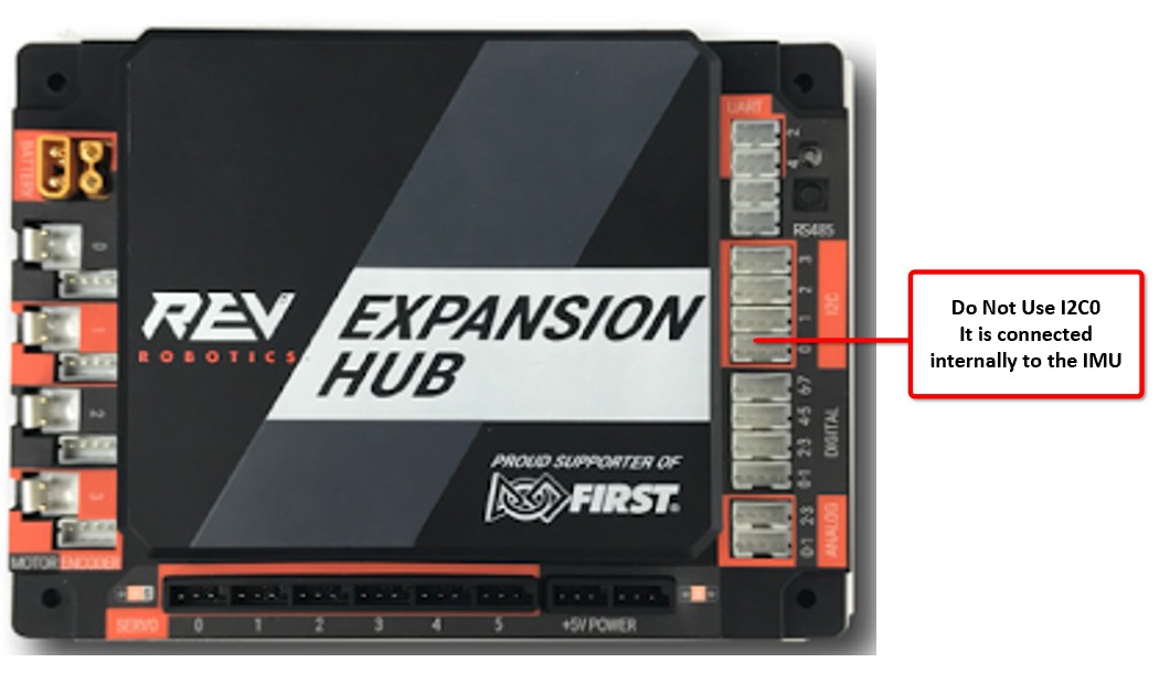
On the Control Hub, I2C bus 0 is shared with the built-in IMU. An external sensor on that bus has to compete with the IMU for the same two wires, which can corrupt the IMU's data, the sensor's data, or both. Plug external I2C sensors into buses 1, 2 or 3.
Plug cameras into the USB 3.0 port
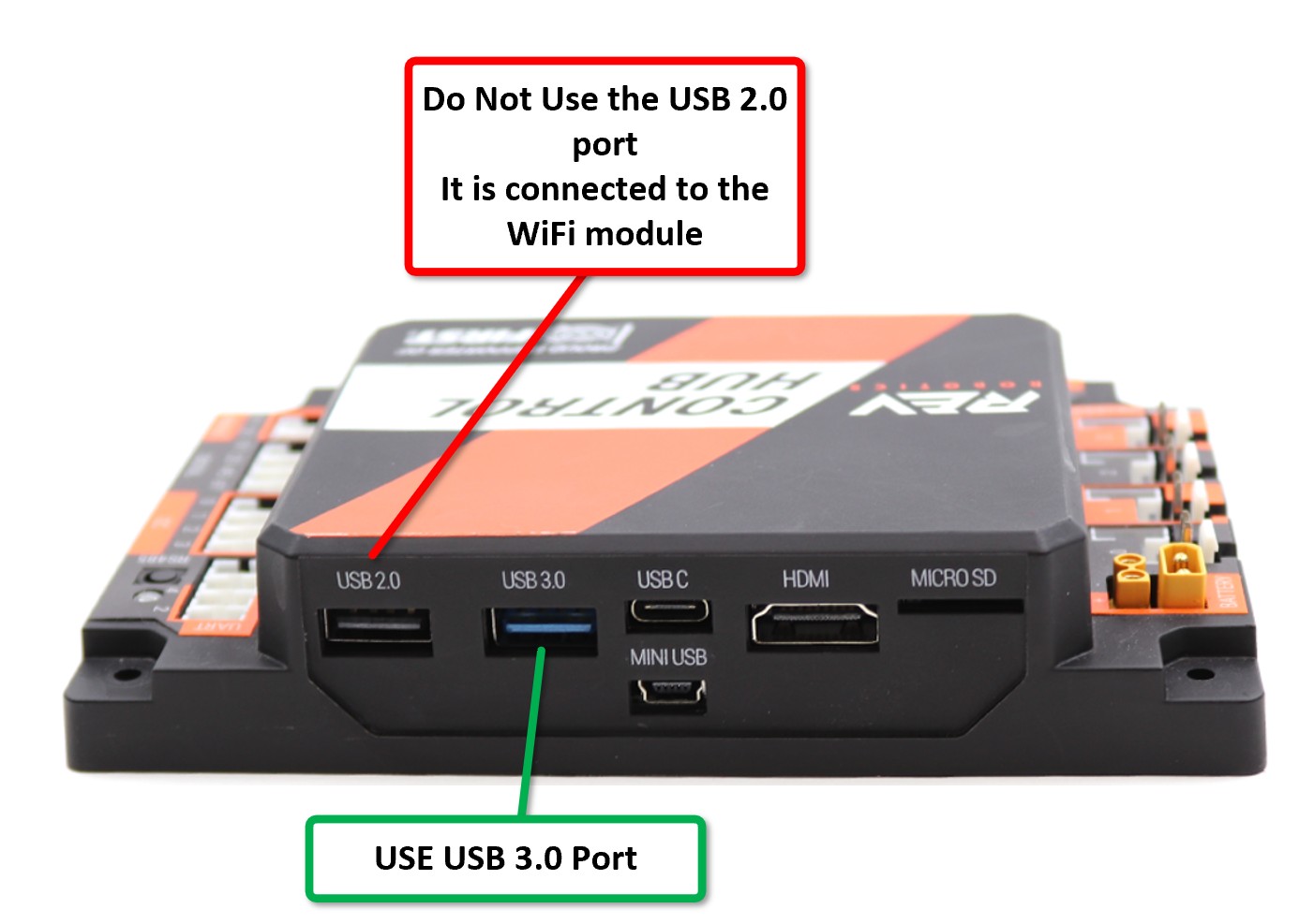
REV and FIRST both warn about this one. A static zap into the Control Hub's USB 2.0 port can upset the Wi-Fi chip, and that looks exactly like a random Driver Hub disconnect. Plug cameras and other USB devices into the USB 3.0 port (the one with the blue insert).
Look after your XT30s
After hundreds of plug-ins, the split pins inside an XT30 lose their springiness. The connector still looks fine, but a bump during a match can break contact for a few milliseconds. That's long enough to reboot the hub.
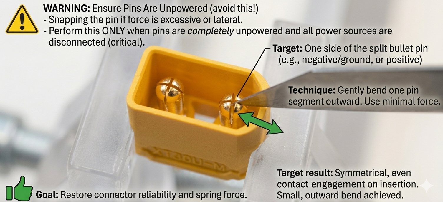
- Disconnect the battery and all power first.
- With a small flat screwdriver or tweezers, spread one half of the split pin very slightly. It's soft metal and doesn't take much.
- Test the fit. It should be snug but shouldn't need a lot of force.
If a pin is bent, cracked or still loose, replace the connector. XT30 pigtails cost far less than a lost match.
Pre-match checklist
Run through this before every competition, and again after any repair. Ticking the boxes doesn't save anything; reloading the page clears them.
If every box is ticked, you've removed most of the electrical problems that plague FTC robots. What's left is usually a bad cable (swap it), old firmware (update it), or a real bug in your code, which you can now chase with confidence.
What you learned
- Three gremlins: ESD crashes the processor, noise corrupts signals, and loose connectors drop power.
- Robots pick up static from the tiles, especially with sliding wheels. Sparks can jump about 10 mm.
- Defenses: isolate the electronics, ground them with an approved 470 Ω strap, add ferrite chokes, and insulate the outside.
- Accordion-fold extra wire, keep power and signal apart, and cross them at 90°.
- Keep I2C bus 0 for the IMU. Use USB 3.0 for cameras.
- XT30s wear out. Re-spread the pins with the power off, or replace them.
References
- Managing Electrostatic Discharge Effects, FTC Docs
- ESD Mitigation Techniques for FTC, Eric Chin (PDF)
- REV Control System troubleshooting, including the grounding strap and USB guidance
- FTC ESD and Wiring Best Practices, kickoff presentation (PDF)
- FTC electrical troubleshooting walkthrough (video)